Sizing scenario
Preliminary sizing
- Based on unsubmited data and information
- Provid data to begin project
- Takes 6 months to one year
- Require the most experienced engineers. (Requires assumptions and judgements based on previous experience)
- Use rapid sizing with rough approximation methods. Complex redundant structures need to be simplified
- Basically hand calculations with help of desktp calculator
- Stress check usually not required
- Analysis may not be neat but must be legible
- Applies for Static analysis but Fatigue and DT shoulb be taken into consideration
Detail sizing (Production stress analysis)
- time-consuming and costly process (takes about two years)
- consists on unsubmited data and information
- consists of detail stress analysis
- based on given structure, materials, loads
- Requires usage of various software
- Requires FEM to determine more accurate load distribution
- applies for static, fatigue and damage tolerance
- MSs should be close to 0 for weight saving
- stress checks are required for important areas
Formal stress report
- consists on submited data and information
- takes over a year
- based on production stress analysis
- must be neat and clean with minimal page count
- Requires checking and approval
- must use approved methods of analysis
- may be revised to make corrections or substantiate a downstrea, derivative airframe.
- should follow stress report form
Requirements
- FAR Part 23 - for airplanes weighing 19,000 pounds or less and with 19 or fewer passenger seats
- FAR Part 25 - for airplanes weighing over 19,000 pounds of with more than 19 seats
Stress engineer finctions
Stress engineer provides designer with required sizing based on loads and materials in use.
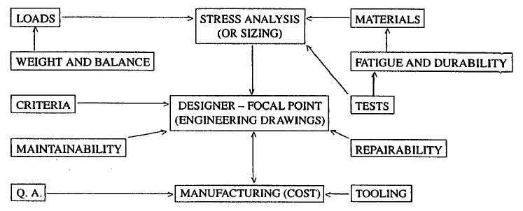
Design considerations
- It's useful to learn about existing desing and solutions
- all sections and parts need to be analysed for flow of loads
- for long-life strucrures detailed desing is extremely important
- assembly proccess shhould be as easy as possible
- avoid shims where nessessary
- keep in mind future structure update
- keep in mind cost, mantainability and repairability
Structural Indexes
For optimisation indexes are very useful
- For shear
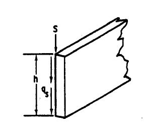
\[\frac{q_s}{h}=\frac{S}{h^2}\]
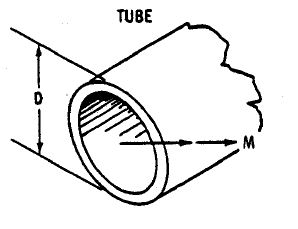
- For torsion
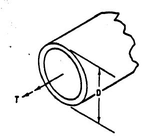
\[\frac{T}{D^2}\]
- For columns
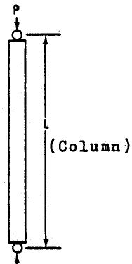
\[\frac{P}{L^2}\]
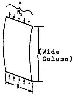
\[\frac{N_x}{L^2}=\frac{P}{BL^2}\]
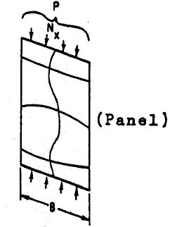
\[\frac{P}{B^2}=\frac{N_x}{B}\]
- For bending
\[\frac{M}{D^3}\]
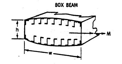
\[\frac{M}{wh^2}=\frac{N_x}{h}\]
Sign convenions
Engineers should use standard sign conventions so that calculations can be read and checked without confusion. Unknown loads should be assumed positive
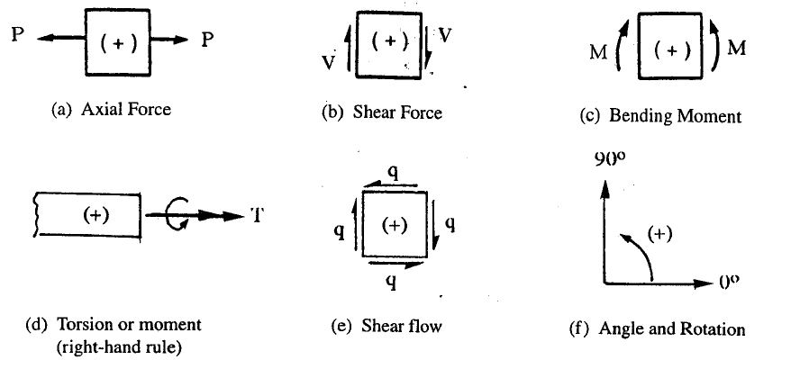
Reaction Loads
The signs used to represent reaction loads are shown below
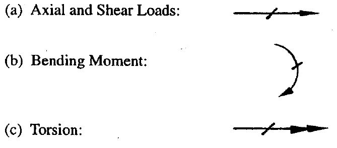
- If the deirection of a reaction is unknown, assume it acts in positive direction
- The reaction loads occur generally at supports
Load diagrams
Load diagram plots are shown below
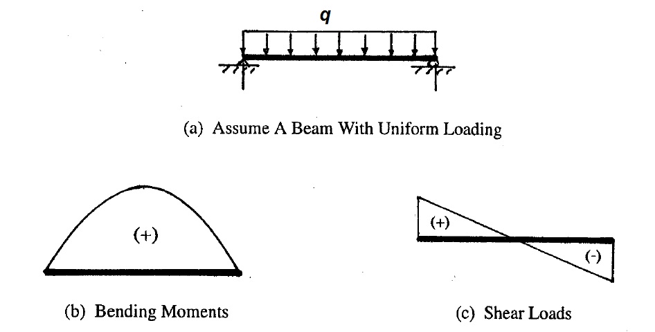
- Positive bending moment diagram is plotted on the compression side of the member
- Positive shear diagram is plotted on the upper side of the beam (outside of the frame
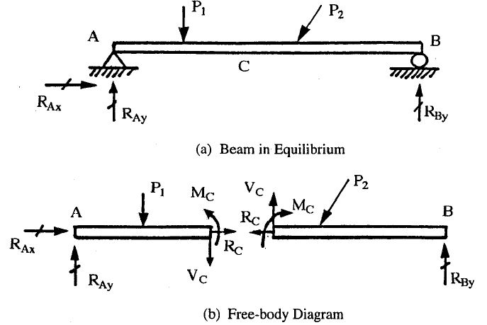
Free-body diagrams
To analyse a given structural member it is necessary to isolate the body by removing all contacting and attached bodies and replacing them with vectors of forces and moments.Such representation is called freebody diagram. It is the first step in the solution of problems in mechanics. If imaginary cut is made, the internal loads at the point become external loads on freebody diagram
Drawing tolerances
In general use nominal dimentions to show positive MS in report. However, if adverse tolerance could signifacantly reduce strength, use the following rule for dimesions Use mean dimension and total negative tolerance nott Exceeding the following vallues: (Niu, Airframe stress analysis and sizing, pg23)
- 10% for single load path
- 20% for multiple load path
Margin of Safety
Unless otherwise specified, a factor of safety of 1.5 must be applied to the limit load \[Ultimate Load = 1.5 \dot Limit load\]
Two checks are required:
- The structure must bu able to support ultimate loads without failure
- The structure must be able to support limit loads without detrimental permanent deformation
Use capital letters for allowable stress (F), moment (M) or load (P). Use small letter for applied ultimate stress (f) moment (m) or load (p).
Margine of safety is calculated as \[MS = \frac{F}{f}-1\]
Stiffner Requirements
Insuffisient rigidity could lead to
- Loss of doors or improper seating of doors due to excessive deflections and adverse tollerance build-up
- Failure of "over center" and "dead center" mechanisms due to adverse tollerances and unaccounted-for deflections.
- Loss of canopies due to adverse tollerancea and excessive deflection.
Design, stress and Structural Dynamics departments should work together to prevent such conditions:
- The stress department is responsible for sufficient control system rigidity and the effect of tollerances should be considered where applicable
- Limit deflections on control devices should be considered
- Structural dynami department often specifies rigidity requirements for various items (EI and GJ values)