System is an integrated set of elements, sub-systems or assemblies that accomplish for a defined objective. Elements could be:
- Products
- Software
- Hardware
- Processes
- People
- Information
- Techniques
- Facilities
- Services
System can be decomposed to elements treated as a black box.
System hierarchy is a way in which different elements of a system are organized and structured. The hierarchy helps us understand how various components interact and work together to achieve a common goal.
Core Concepts of Systems Engineering
Systems engineering has evolved significantly, addressing the complexities of modern product development. The practice aims to mitigate risks associated with complex systems, focusing on the connections between components.
Lifecycle
Each product has the following stages
- Concept
- Development
- Production
- Utilisation
- Support
- Retirement
Processes behind life-cycle are dinamic, iteractive and recursive.
Iteration - repeating process to improve product by using newly available information
Recursion - applying the same process at finer levels of details (for exaple decomposing system to the elements
Life-cycle methods:
- Waterfall method- specified, sequential process that follows a predetermined sequence. Used than requirements are defined and will not change in future
- Incremental and iterative method - after each step product is checking for meeting expectation. If meets - new requirements are to be defined. If not - product improves to meet expectations
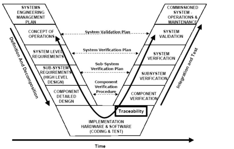
- Vee method - product evolves over time from stakeholders requirements, to the system concept and finally to elements design. At first system is decomposing, than components are developed and verified and than components are integrating to a system. Iteration is optional after components integration
Lifecycle process categories
All life cycle processes (about 30 in 15288 standard) can be splitt in four categories
- agreement processes - formalize methods and expectations between organization. They needs to define responsibilities, project and technical functions.
- organizational project enabling processes - focused on needed resources to accomplish goals. They needs to define environment in which work is performed, project processes and lifecycle model in use, required resources to accomplish project and quality measurement processes
- management technical processes - focused on managing allocated resources to reach the goals. They need to track costs, and milestones, to align efforts with plans and to correct planning to avoid shortfalls.
- technical processes - focused on technical tasks at any point of life cycle. They need to realize and apply the processes to create the system which meets stakeholder requirements.
Cost of Corrective Actions
A study highlights that correcting issues during the requirements phase is significantly cheaper than making changes later in the design, build, or testing phases, with costs increasing dramatically at each stage.
| Development phase | Relative cost of corrective action |
| Requirements | 1 (reference case) |
| Design | 3 to 8 times |
| Build | 7 to 16 times |
| Test | 21 to 78 times |
| Operations | 29 to 1,615 times |
Return on Investment (ROI) in Systems Engineering
Higher levels of systems engineering capability correlate with better project performance, with a study showing a 57% success rate at high capability levels. Investing around 14% of total program costs in systems engineering yields a substantial ROI of of 7:1, with projects lacking systems engineering seeing a much lower median investment of only 7% there is a 3.5:1 ROI
MBSE
Model-based system engineering is a formalized application of modeling to support system requirements, design, verification and validation thru all lyfecicle of the development
Key concept is model-based definition (MBD) which used to define system in digital format (cad models, manufacturing and performace models)
MBSE focused on is focusing on development, management and controlling system
Using MBD thru entire enterprise reduces cost, improves performance and open way for easy product improvement:
- improves communication between deweloping teams
- improves quallity
- reduse time and cost for test and integration
Models
In the context of systems engineering, a model that represents a system and its environment is of particular importance to the system engineer who must specify, design, analyze, and verify systems, as well as share information with other stakeholders
Models can represent physical form, functionality or behaviour. Different models are using different programs with
- its own language with unuque rules and objects (constructs) to build the model (abstract synthax)
- set of symbols to represent objects (concrete synthax).
- semantics to provide meaning of the objects
Functional modeling languages consists of:
- Data flow diagrams (DFD)
- Integration definition for structural modeling (IDEF0)
- Enhanced Functional Flow block diagram
Structural modeling technics includes:
- Data structure diagrams
- Entity relationschips diagrams
- Object modeling techniques
System engineering works with Systems Modeling Language (SysML) which overlaps with Unified Modeling Language (UML).
It is important to use verification of the model when applying MBD.
Verification ensures you build the system right and validation is that you build the right system
SysML
UML is a software engineering modeling language enabling communication and visualisation with respect to program structure and details.
SysML is a graphical modeling language developed to support system engineering. It is human-readable and and supports XML and AP233 data exchange formats for mashin readability.
SysML builds uppon UML and they have many in common. SysML allows to modify 3 diagrams
- activity - focuced on behaviour - specified transformation of inputs to outputs thru conctrolled system of actions
- block definition - focused on structure - describes the relationschips between blocks
- internal block diagram - structure - desctibe internal structure of the block in terms of parameters and connectors
And adds 2 diargams
- Requirement
- Parametric - structure - ise to express constrains and equatuons
Also SysML extends UML
- Item flows
- Value properties
- Allocations
UML diagrams(?):
- Sequence diagram - behaviour - provides representation of a messaged-based behaviour
- State machine diagram - behaviour - represents lifecycle of the blocks and event-based behaviour
- Use case diagram - behaviour -provides to dedcribe functionality of the system in terms of goals or means
- Package diagram - structure - used to organise system using hierarchi and can add user - defined properties (verification methods..)
Top level requirement diagram - represent text-based requirements
Four pillars of SysML
- Steucture
- Behaviour
- Requirements
- Parameters
To implement SysML used Continious Product Improvement Stategy to gradually implement components of the process.
Existing systems:
- Magic draw
- Tau and Rapsody
- Artisian Studio
- Visio
Model-based enterprise (MBE)
Model-based enterprise is an integrated, collaborative environment, founded on a model-based definition that is shared across the enterprise, enabling rapid, seamless, and affordable deployment of products from concept to disposal
MBE is using computer-based technologies to build integrated and full system that represent a single source of truth using linkage between Program Data management (PDM), Product Life-cycle Management (PLM) Manufacturing process management (MPM), Manufacturing Execution System (MES) and Enterprise Resource Planning (ERP)
Using single set of data for different departments reduce costs, minimise interpretation errors and delays and helps engineers focusing on product improvement.
3D models if STEP (ISO 10303) JT (siemens) and 3D PDF (ISO 32000) formats can contain not only geometry but also information about matetial, tolerancing, surface finisching and so on.
Digital thread is a raw data (files, data pathways) that generated through a lifecycle of the product. Using digital thread can increase efficiency of development and make product more competitive. For this purpose uses Digital Integration of Design and Production thay ties together PLM, ERP, MES and MMP. Digital thread helps to automate the prosesses (e.g. transfering data from engineering to production without a human behind it). Single source of information in model-based definition helps in
- exchange
- visualization
- communication
During design Model Base Definition begins and evolves until product is fully defined by means of PLM system. During production stage annotated model is sending to manufacturer using Technical Data package (TDP) using formats like STEP or JT.
Implementation of MBE introduction could be
- organisational culture that is sticking to 2D drawings
- focus on short-term return on in investment
- need to adopt standard practises
- need to investment in software
- software maturity
MBSE Framework
To use MBSE the framework is required. Frameworks can be focused on a single component, or series of components
Analysis framework consists of variety of simulation tools: Nastran, ANSYS, MathLab. It should be able to transfer automatically results from one analysis to the subsequent. Framework should have execution engine to iterate analysis until requered solution reached. It can also include version control to update elements without impacting the architecture of analysis. In some frameworks results can be checked against requirements.
Examples:
- Siemens HEEDs is an example, that can search alternative design configuration
- LMS Imagine Lab - automate mechatronics systems creation
- Phoenix integration model center
- Dasault iSight - optimisation and design of experiments
Resources for Systems Engineering
Key resources include
- INCOSE Systems Engineering Handbook,
- SEBoK,
- ISO/IEC/IEEE
- 15288 standard, and the
- NASA Systems Engineering Handbook.
These resources provide a comprehensive understanding of systems engineering principles and practices. Understanding Systems and Their Architecture