Symmetrical
Use the common maneuver V-n diagram ('V' - speed, 'n' - load factor) to represent the maneuver load requirments for an aircraft. Because the effect of compressibility on wing lift and the effects of varying air density on aircraft speed capability, V-n diagrams have different shapes at different attitudes. All critical combinations of altitude, weight and c.g. travel position must be investigated
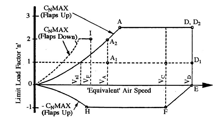
Within the limits of the diagrams the aircraft must be checked for both balanced and pitching maneuver conditions. In a balanced condition the aircraft is assumed to be in equilibrium with zero pitching acceleration. This can be achieved in a steady state pull-up or turn. All critical points around the peripheryof the diagram must be checked for this condition.
Flap-up case
For airworthy transport category aircraft, design to a minumum positive limit load factor of 2.5 and negative load factor of -1.0
Flap-down case
Flap-down maneuver requirements are derived in the same way as those for flaps-up except as affected by the following differences:
- Because the greated lift coeficients are possible with flaps-down, the aerodynamic lift curve is steeper
- A maximum limit load factor of 2.0 is required.
- The V-n diagram is limited by a speed \(V_f\) which is equial to the stall speed multiplied by a factor of 1.6 or 1.8 depending on the aircraft weight condition and flap setting
Unsymmetrical
Rolling Case
Rolling occurs due to the application of roll controll devices and it is unbalanced moment about the aircraft c.g. that is to be reacted by aircraft inertia forces. The effect of wing torsional deflections on the rolling effectiveness of the ailerons and spoilers must be accounted for.
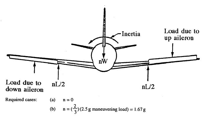
The ailerol and spoiler deflection requirements at each of the required speeds are as follows:
- At \(V_A\) sudden deflection of ailerons and spoilers to stops (limited by pilot effort)
- At \(V_C\) ailerons and spoiler deflection to produce roll rate same as above at \(V_A\)
- At \(V_D\) ailerons and spoiler deflection to produce roll rate \(1/3\) of above at \(V_A\)
Yawing Case
The yawing maneuver occurs due to rudder deflection and produces three design requirements:
- with the aircraft in unaccelerated flight at speed \(V_A\) (the design maneuvering speed), and at zero yaw, the rudder is suddenly displaced to the maximum deflection. This causes a high yawing acceleration
- the aircraft then yaws to a maximum side slip angle. This is a momentary dynamic overyaw condition
- with the aircraft settled down to a static side slip angle, the rudder is the returned to neutral